Posts

Showing posts from 2013

Brake fixed

Image
I put the caliper back on the car, bled it and pumped like mad and eventually the piston came loose. Back on the bench the problem turned out to be rust around the lip on the caliper casting where the piston fits. The piston had a little surface corrosion, but this cleaned off with wire wool and some 4000 grade wet-and-dry. I took a cone grinder fitted to my Minicraft drill to the lip on the casting and lo-and-behold the piston was sliding freely in and out again. The only problem was the replacement dirt gaiter which no amount of pressing and poking would convince to stay firmly down on the caliper. Investigation showed this to be due to more corrosion which I did my best to clean up. The caliper is now back on the car, bled and working as it should. It isn't perfect, but it will be fine while I scope eBay for a replacement.

RX4 Brake Woes

Image
The front nearside brake caliper has been sticking for a while.  It took a month to get a reconditioning kit from Renault, but taking the caliper off takes 5 minutes. Problem is getting the piston out. I've tried 3 different bodge methods to no avail, but putting the caliper back on the car and pumping the brakes came closest, so I'm going to try that again tomorrow. After that hopefully a good clean with fine wet & dry emery and fit the new seals and I'll get another few months out of it.

2. 5 Inch Raspberry Pi Silliness

Image
Mike on Freegle kindly gave me this neat little LCD TV he'd finished with. Now that analogue broadcasts have stopped and 4G seems to be the future for watching TV, these old sets are obsolete, but this one has an A/V input so it can be used as a dinky monitor. It's a bit small for raw Raspberry Pi, but I want to try it with the Arduino TV-out library to see what that could do. If I ever got the hang of GUI coding it might be possible to make something with big buttons. 

Mining Raspberries

Image
Finally found a use for the Raspberry Pi. Finlay was introduced to Minecraft on the school iPad, but since we don't 'do' Apple (spits in disdain), we have it running on a Raspberry Pi (old 256Mb version). Going to try it with a Bluetooth keyboard next. Must get around to trying XMBC too.

Black Pipe Radiator

Image
This is my experimental mini radiator for the downstairs loo made from scrap 28mm copper pipe and some spare fittings. I got the idea after finding an old photo of the bio-fuel heat exchanger I made almost 10 years ago. It's painted matt black to maximise radiation (finally found a use for O-level physics). So far it isn't working too well. Airlock is one problem I need to consider, but I also have a suspicion that the TRV valve may have stuck after more than a year screwed down closed. I'll investigate further. UPDATE - Seems to have been an airlock which has cleared itself elsewhere in the system, hopefully right to the top!

Handy Portable Hard Drive

Image
This neat portable hard drive is just 80GB, but it cost under £3. The drive itself was salvaged from a laptop that had come to the end of its useful life and I got the aluminium case with USB/SATA adaptor on eBay for just over £2 including postage all the way from Hong Kong. The brightly-coloured protective soft case was courtesy of my darling other half (it was a make-up bag of some sort!) and is just the right size for the drive. Home brew portable hard drive 

Solar Panel Installation

Image
Solar panel installation at Trengwainton Garden, a National Trust property in Cornwall. I really like this approach and it has got me thinking about going back to building a single panel collector using the old patio door double-glazing unit I've been hoarding for the last 3 years.

Edge-lit Display Decoder Test

Image
The display is being illuminated using 10 white LEDs salvaged from a £1 string of battery-powered Christmas lights.  This is a very cheap way to get white LEDs with flat tops and I found 30 more LEDs on strings like this so that's enough for 3 more digits. The decoder takes a 4-bit binary-coded decimal (BCD) value and uses a 74HC138 to decode 0-7 and a 74HC00 to decode the remaining 8 and 9 digits (values above 9 are meaningless in this set-up).  To test the circuit I connected a rotary BCD-encoded switch I've had in the spares box for almost 20 years.  The switch goes from 0-15 (decimal) coded in 4-bits and the flickers to 0 you can see in the video are caused by the switch breaking before make. This is the hard work done.  Using 2 more HC chips and a ULN2803 I can build a simple 2-4 line decoder with increased current handling. This will allow a PIC or Arduino to multiplex drive 4 displays using just 6 output lines. I might even use an old 16F84 I have as an I2C slave to

Arduino DS18S20 With LCD

Image
Arduino lite ATMEGA-16 test circuit with a DS18S20 temperature sensor and a 2x16 character LCD display. Using the Arduino libraries this is very straightforward. The green LED is lit when the temperature is below 25 C and the red LED comes on if the temperature goes above 25 C.   The small LCD panel was salvaged from an old specialist printer and as well as a 'Power' LED there is another green LED and a red LED on the panel along with the required resistors.   The DS18B20 sensor IC mounted on the breadboard.  The big blue potentiometer is for setting the contrast on the LCD display. Video of this working - http://www.youtube.com/watch?v=VHk5Idpl5WE The next steps are to get 3 sensors working with this circuit and then to see if I can get the 2-wire option working, which would be a handy improvement.

Skoda come, Skoda go.

Image
Well, we bought a much newer Skoda Fabia a few weeks ago and after much soul-searching I decided to give the Renault RX4 a chance and get rid of the old Fabia (MCZ).  This was no easy decision because the Fabia has been incredibly reliable and is still going strong at just short of 160,000 miles with no engine problems.  The problem is that it is handy to have one larger car and having spent £750 on a new turbo for the RX4 it seemed daft to sell it, so there you go.  I switched the insurance over to the Renault yesterday and the old Fabia will be off to the vehicle dismantlers (i.e. scrappie) tomorrow. I will almost certainly have a tear in my eye and I definitely do not want to be around when they start pulling her apart! I quite fancy one of these though, once I've saved enough up to buy a second-hand one.

Experimental electromagnet valve

Image
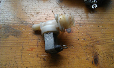
Mains water valve salvaged from an old washing machine that was fly-tipped at a beauty spot about 3 years ago. I stripped it and took the carcass to the dump. Civic-minded and eco-friendly all rolled into one. Experimental 12-volt version using a quickly (i.e. badly) wound coil using wire taken from an old home brew motor that was never finished.  It works after a fashion, but would probably need a proper tightly-wound coil to be effective. The valve opens when 12 volts is applied, but not fully.  The resistance across the coil is about 8.5 ohms which I think is a bit low for this type of coil. It was an interesting wee experiment and I might develop it sometime if I get more suitable wire.

Interesting Display

Image
This is just a taster. This is an interesting edge-lit numeric display from the 1960s, a successor to the Nixie tubes. The arrival of 7-segment displays in the late 60s probably made these ones obsolete so they are quite rare. Each digit 0-9 is inscribed on a thin piece of transparent acrylic and these are sandwiched together. Each digit can be illuminated by its own 28-volt bulb. Nowadays bright white LEDs are the alternative to small bulbs so here we have the digit '8' being lit up by an LED driven from 5 volts. More to follow.

MR2 Dashboard tinkering

Image
Being a 1980s car, the MR2 doesn't have a DIN radio slot or ISO connections for car audio. The surround had been butchered at one point years ago to try and make a CD player fit and looked grim. On top of that the lid for the ash tray had fallen off and as nobody is going to smoke in the car I took the ash tray and lighter out and stuck the lid down permanently with epoxy. So I needed a 12-volt socket to charge my 'phone and to neaten up the radio surround. I got this lightweight radio in Lidl on offer. It has no CD, but plays back from SD cards and USB devices, which suits me for a summer car. Power output is low, but I'm putting a power amp in my centre speaker cabinet along with a pair of better speakers, so not a problem. All 4 outputs can drive the MR2's own speakers. The red panel will be covered in black vinyl from a big old handbag I got for 50p in a charity shop and the 12-volt sockets are a £1 adaptor from Poundland. Only drawback at present is the USB h

More tool bodging

Image
  Taking the throttle body off the MR2 is a pretty simple job with one exception.  There are 2 coolant hoses that go in and out of the Idle Speed Control Valve (ISCV) which are a pain in the backside to re-fit as there is so little space in the engine bay.  This is the real problem working on this car because everything is so tightly fitted in.  Anyway, after spending about 30 minutes fiddling with the hose clips I came up with the idea that I needed pliers with an extra wide nose to crimp the clips open so I could get them back up the hoses.  A bit of searching in my scrap boxes and I found these 2 threaded clips which I pushed onto the pliers.  DIY extra wide nosed pliers.  Job done in under 5 minutes with these!

Power Window Repair

Image
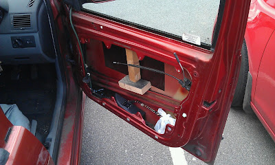
The power window mechanism suddenly stopped working on my Skoda last week and the window dropped into the door.  A bit of bodging with some bits of wood kept the window closed tight while I waited for the replacement parts to arrive.  It turned out that one of the plastic sliders had broken and that had allowed the cables to go slack so one of them had screwed itself up round the winding mechanism. The mechanism is common to several Skoda, VW, Audi and Seat models and the spare parts were very easy to get and also cheap.  The inner panel came off easily and everything made a fair degree of sense so it was easy to work at. I also discovered the speaker in the driver's door had dozed, probably due to water getting in over the years, but as luck would have it I had recently acquired an identical spare speaker, so I swapped that out as well. The door with the temporary bodge to keep the window closed.   The old winding cables before being replaced. The new wi

TV output from Arduino

Image
Little video showing a 7-inch LCD monitor connected to an Arduino running the TV-Out library.  For this test I connected a Manifold Air Pressure (MAP) sensor directly to the Arduino using analgue pin 0 (AN0) to create a bonkers boost graph.  Sucking and blowing on the pipe makes the bar graph change.

Start Up Logos & Tachometer

Image
 MR2 Black-and-White Image I got bored today and started mucking around with a start-up logo for the vehicle data system.  The Arduino TV-Out library has a neat 'Bitmap' function that will load a properly encoded 1-bit image into the image buffer.  I spent a bit of time on PhotoShop working on a photograph of an MR2 until I got reasonable 1-bit black-and-white picture.  This was converted to a C++ style array using Image2Code, a neat little application and with a bit of editing, this was included into the Arduino sketch (program). The result is pretty good for a 1-bit picture at 184 x 72 pixels and extremely Sinclair ZX81 retro.  The idea is to have this as a start logo and also for display when the system is in any idle mode.  It looks a lot sharper on a 6-inch or a 7-inch screen too. I also got the Tachometer routine working on the 18F4520 PIC microcontroller.  It counts the time between pulses arriving on the INT0 interrupt pin and the inverts the time to gi

Battery Conversion

Image
I have nearly finished converting the battery in the MR2 from the piddly little 35Ah to a bigger 55Ah one. There were a few considerations with this. The battery terminals were too small, but I got the big ones in Halfords along with new earth cables. I also discovered that all the time I've owned the car the engine earth strap was disconnected which explained why the car was so hard to start! A trip to a scrap yard got a battery bottom clamp (off a Citroen) for a fiver and I made up my own rear clamp. The battery is clamped in securely and isn't going anywhere, but the big problem is the intercooler which is supported by the existing battery top plate (red thing below). If this wasn't the case I could lose the plate because it isn't really necessary, but then the intercooler would be flapping about a bit. As a stop gap I've bolted risers onto the plate because the new battery is 20mm lower than the old one and the top plate needs to be level, but I'm g

Where it all began

Image
This is pretty much where my interest in microcontroller, computer interfacing and all the rest of it really began, way back in the Spring of 1989.  I had been interested in electronics since I built my first radio when I was about 13 or 14 in the late 1970s and I'd learnt to program on a borrowed ZX80 a couple of years after that, but this was my first proper interfacing project. I was living in Wembley at the time, an impoverished student teacher and one of my tutors suggested a cheap robotics project might be interesting as a way into Logo and this was the result.  I used to make weekly trips on the Tube up to the Maplins in Edgeware to buy whatever I could afford.  I already had the Spectrum and brought that over on the 'plane from Belfast at some point.  The 'monitor' is a Sinclair Microvision, no word of a lie.  I used a 12-inch portable for the programming, but designed a user interface with huge characters, 4 times the height of the normal ones so they could

Shady tree mechanics

Image
  My 2001 Skoda Fabia workhorse started acting up today.  It is a very reliable wee car with 155,000 miles on the clock now.  The engine is the simple and tough 1.9 SDI diesel so there are few things to go wrong with it and the same engine in the Octavia is much sought after by taxi companies where the cars go on to 300,000 miles in some cases.  Anyway, it was doing the kangaroo diesel routine again and the usual suspect for this is the exhaust gas recirculation valve (EGR) which becomes clogged up with soot especially if there is poor fuel or crud in the tank.  It's a 30-minute job to clean it out with some carb cleaner, but you need a 6mm hex bit to get it off and when I went looking for mine I realised I had lost it down in the engine the last time I did the same job.  Clever. Anyway, after some standard swearing at self and some pondering it dawned on me that I have a wee box full of Allen keys that I have kept from flat-pack furniture jobs and the like and there were

Power Of Three (Things)

Image
  I finally got it working tonight. PIC --> Raspberry Pi --> Android App PIC is reading 8 analogue ports and outputting the data every 0.1s via serial over USB.  The Raspberry Pi is running an Apache server and in response to an HTTP request to a PHP script, it reads the serial data and re-formats it into a simple fast JSON array.  The Android tablet is running a custom app from App Inventor to make the HTTP request, get the JSON response and display the data. The next step is to get a nice bar graph interface working and set up the Manifold Air Pressure (MAP) sensor I have in the car so that the thing can be tested reading boost from the supercharger. Oh yeah and I have to get the Raspberry Pi working as an Access Point (AP) again.  I did this before okay, but with a different wi-fi dongle.  This is critical to using it in the car to send point-to-point data to the tablet.

PIC Datalogging With Added Raspberry Pi

Image
Here we have a PIC 18F4620 in data logging mode collecting analogue values from 8 ports and outputting them serially via the USB bridge.  The software formats the 8 10-bit analogue values into a 'frame' like this - {HLHLHLHLHLHLHLHL}[CRLF] and these are sent every 1/10 of a second at a baud rate of 115,200.  The H is the top 5 bits (most significant) of the analogue value and the L is the bottom 5 bits (least significant).  To add clarity when testing, I added 40h (64) to these values to make them printable characters instead of control ones so the data frames can be viewed in the Putty terminal program. This is Putty running on the Raspberry Pi receiving the data frames from the PIC.  The text 'SERIAL READY' is sent after a reset and is also a useful test. What next?  Wait and see, but the clues are Apache, PHP5, Android and access point. Need a cup of coffe now.  And some heat, for May it is freezing here in Northern Ireland and my wife

LED Backlighting Update

The monitor was knackered although the backlighting using LEDs worked a treat. Really good practice doing the conversion though, so I'm going to look at the 21-inch rescued TV next.

LED Backlight

http://www.flickr.com/photos/44653173@N00/sets/72157633242265497 This is just a first attempt at upgrading a monitor to LED backlighting.  The power supply for this monitor seems to be busted after all, it isn't working once it is under load.  I'll test it with a PC power supply later. Unfortunately I managed to break one little connector when I was taking the monitor apart, but this may be repairable, I'll have to see. The light output from the LEDs is fairly even and the only downside for now is no brightness control, but that should be possible to address if need be.

String of LEDs

Image
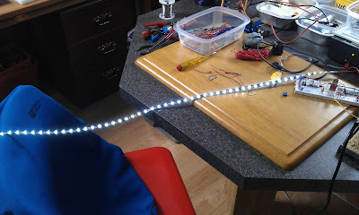
These are hopefully going to replace the cold cathode backlights in the second Hanns-G monitor I picked up, which has a failed inverter board. This is a 1 metre strip containing 60 LEDs and running off 12v and cost £5 delivered. The strips can be cut every 3 LEDs and there are copper pads for soldering to. If this works I'm going to convert the other Hanns-G monitor, the 21 inch TV I rescued from a ditch and the 7-inch LCD monitors to LED backlights. Buying longer runs of LEDs, the cost gets cheaper so 5 metres with 300 LEDs is only £15, enough for lots of backlights.

Raspberry Pi and DS18B20

Image
  This is just a test of the Raspberry Pi hooked up to a DS18B20 temperature sensor.  Using LadyAda's tutorial, this was up-and-running in about 5 minutes and sending out highly accurate temperature data over the network.  As it is much more expandable and easy to use than the LM75, I think this will have to be the weapon of choice for the heating control system.  My only concern is whether the Raspberry Pi can really be used for a 'mission critical' application, bearing in mind that today the there has been an ice storm raging across the UK which has been particularly bad here in Northern Ireland.  This would not be a day to have the heating control fail due to an OS crash!

Improved Thermometer

Image
An improvement on the thermometer, this is a lot more practical. I connected up my big 7-segment LED module, added the Arduino library and one extra procedure and very quickly had this thermometer with a big bright display and accurate to 2 decimal places.  I took the picture with the flash which is why the display doesn't look so bright, but trust me, it is. The pint milk carton is to give an idea of size.  Looks like we need milk too. A better photo without the flash showing the LED display in all its glory.

Massively over-engineered thermometer

Image
Went a bit daft tonight and tried out the Arduino TV Out library along with the 1-Wire library to make a slightly mental video screen thermometer.  The temperature here is 17.68 ℃ expressed as 1768 hundredths of a degree.  The DS18B20 has a very impressive 12-bit resolution so it is accurate to 0.625 degrees Celsius allegedly.   It works well enough for a bit of fun, but the TV Out library relies on accurate interrupts to get the video signal timing right and while it is fine on its own, the complex polling of the 1-wire bus must be disabling the interrupts because the screen flickers badly each time a temperature update is performed. The flickering screen reminds me of the ZX80 or the ZX81 in 'fast' (i.e. rubbish-looking) mode, which isn't surprising because the Arduino is in a similar class to the Z80, except twice as fast and with a lot more memory than either of the original Sinclair computers. I'm thinking of converting one of the 7" LCD moni

One Wire is all you need

Image
I ordered up a handful of DS18B20 1-wire temperature sensors and here is one interfaced to my DIY Arduino board.  There are some nice sample programs available to demonstrate the capabilities of the 1-wire (Dallas/Maxim) interface bus with the DS18B20 and this one is outputting the data to a PC via the serial port (USB) The odd thing beside the sensor is a re-usable plastic ice-cube I'm using to cool the sensor down for testing! This is the output on the PC via the serial monitor. The beauty of these sensors is that they can be chained together on the one bus as each one has a unique laser-etched hex serial number to distinguish each one.  This seems to be the way to go for the heating control system as it will have 4 sensors positioned on the water pipes and the hot water cylinder for monitoring.

I Have Wood

Image
Just a quick photo of our ecologically sound recycled wood pile. This is roughly 2 loads, each load being a fill of one of those big builder's sand bag (a big bag, not a big builder, well it might be a big builder...). This should last us well into April hopefully. The wood is heavily compressed chips used to make big industrial pallets for machine parts. It doesn't soak up water much so stays dry under the tarpaulin. Warm and toasty.

Big Seven Segment Display

Image
I finally got around to finishing off this prototype 7-segment display module, based on the MAX7219 integrated circuit. I went for the largest displays that the IC can drive directly, but that meant wiring them all together. I've since acquired a slightly smaller 4-digit display which will be a lot easier to wire up. My home brew Arduino is,driving the module, but there are libraries in JAL for PICs for the MAX7219 as well as for the Arduino. The interface is a simple SPI type and could be driven from the Raspberry Pi except that the 3.3v/5v issue becomes a pain in the rear as usual. I'm keen to have this bad boy on the dashboard of the MR2 sometime soon.

Raspberry Pi Server improvements

Image
First of all, I invested £7 in a micro wi-fi dongle for the RaspberryPi, which you can just about see in the photo above plugged into the upper USB port.  It is low-power and very low-profile and makes the RaspberryPi server very neat.  For basic temperature sensing, all that would be needed would be a 4-core cable from the LM75 sensor to the RaspberryPi and 5-volt power and that would be it, a device that can log and send data from anywhere within range of a wi-fi access point. Now, it dawned on me last week (luckily after only 3 hours) that I was writing a small file out to the SD card every 5 seconds from my Python program which might be hard on the SD card with all those writes.  SD cards and Linux file systems provide some sort of wear levelling, but any application which writes intensively to the card is going to wear it out fairly quickly.  Writing to the card every 5 seconds might wear it out in a few weeks at best. There are 2 possible solutions, which seem suited to dif

Upgraded Raspberry Pi Temperature Server

Image
I've been having a lot of fun messing around with the Raspberry Pi as a server and decided to upgrade the temperature monitor with some more advanced I2C shenanigans. I got 10 LM75 I2C temperature sensors on eBay for less than £3 including the delivery, which was a real bargain.  The only drawback was that they are SOIC-8 (i.e. tiny) 8-pin packages, but a small piece of tri-pad copper board and some fine soldering and I was able to come up with the adaptor in the photo below for prototyping purposes. The red LED is just to confirm that 3.3v power is getting to the LM75 on the little breadboard and the white and grey wires are the SCL (clock) and SDA (data) lines for the I2C bus coming from the Raspberry Pi. http://wiltec.no-ip.org (if the server is running, you'll find it above!) Reading temperature data from the LM75 is very simple, but I have hit a minor snag.  The LM75 uses a 2 byte data format although the device is essentially 8-bit.  Only 1 bit in

Retro Sci-Fi Fonts

Image
I started looking at the classic fonts used in 1960s and 1970s science fiction and identified Eurostile and Futura as the fonts I remember best from films like '2001,' 'Silent Running' and TV series like 'U.F.O.' I got to thinking how cool it would be to have indicators using these fonts and how to go about making them.  A bit of experimenting and I found that printing the image above onto a transparency made a good indicator which would allow light to shine through the lettering.  The only problem was that the printer couldn't get a deep enough black.  So I figured, print 5 copies of the image, line them up carefully and glue them together to make a transparency 5 times thicker and the black background is really well, black, but light can still shine through the lettering.  A piece of thin white paper behind it all acts as a diffuser and then all that's needed is a good bright LED to finish it off. I've been playing with this and I'll get

RaspberryPi Micro Server

Image
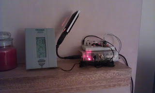
RaspberryPi micro temperature server, sitting on the mantelpiece serving temperature data out via wireless onto the World Wide Web thingy.  Not always on, but if it is, it can be found at Temperature Sensor I'm working on making the readings more accurate using a better Python script.  The thermistor is (very) non-linear so I'm trying to generate a look-up table to do this quickly.